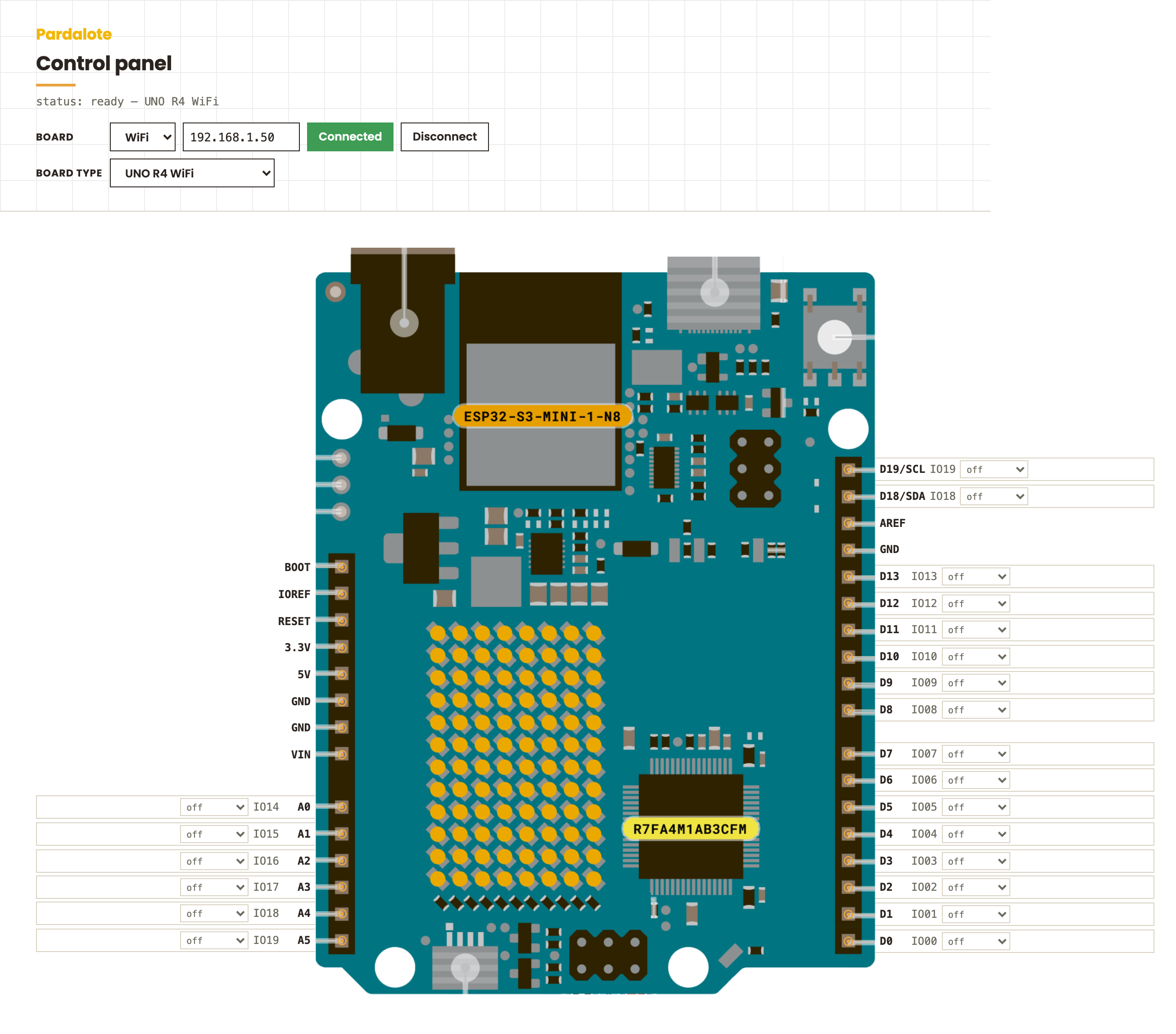
Control Panel
A browser-based control panel for interacting with Arduino pins in real time. Each pin is displayed as a row aligned to a photo of the board. Select a mode from the dropdown and the controls appear. Use the control panel to test your Arduino and circuit.
What You Can Do
- Read digital inputs and see HIGH / LOW update live
- Toggle digital outputs HIGH or LOW from the browser
- Drive PWM outputs with a slider
- Watch analog inputs as a live bar graph
- Open the panel in multiple browser windows simultaneously — all windows stay in sync
Hardware Requirements
- Arduino UNO R4 WiFi or ESP32 development board
- Arduino and browser must be on the same WiFi network
No additional components are needed to use the panel — just an Arduino with Pardalote firmware running.
Setup
1. Upload the firmware
-
In Arduino IDE: File → Examples → Pardalote → minimal-pardalote (or any other Pardalote example that includes the extensions you need)
-
Select your board and upload
-
Open the Serial Monitor at 115200 baud — on first boot Pardalote asks for your WiFi credentials:
=== Pardalote ===
No WiFi networks stored.
=== WiFi Configuration ===
[a]dd  [d]elete  [c]lear all  [s]how  [x] exit
> a
SSID: YourWiFiName
Password: ********
Saved: YourWiFiName
> x
Credentials are saved to EEPROM and survive re-uploads. Press
win the Serial Monitor at any point while the board is trying to connect to update them.Prefer compile-time credentials? Uncomment the two lines in
secrets.h:Arduino#define SECRET_SSID "YourWiFiName" #define SECRET_PASS "YourWiFiPassword" -
Find your Arduino's IP address:
- UNO R4 WiFi: scrolls across the LED matrix
- ESP32: printed in the Serial Monitor
2. No code editing needed
The IP is entered on the page, and the browser remembers it (along with the last board shown) — a returning visit reconnects automatically.
3. Open the panel
Open index.html in a browser, then click Connect.
Using the Panel
Connecting
Enter your Arduino's IP address in the Board IP field (if it's not already there) and click Connect. The status line reads ready once the connection is up; Disconnect stops it and pauses auto-reconnect.
No WiFi? Use the cable. Switch the dropdown from WiFi to USB and click Connect — the browser (Chrome or Edge) shows a port picker the first time and remembers your choice afterwards. The sketch side must start the serial transport: Pardalote.begin(PARDALOTE_SERIAL) (one commented line in minimal-pardalote). Everything else on the panel works identically.
The board layout switches automatically to match the connected Arduino. If you want to view a different board layout, use the board selector dropdown.
Board selector
Three boards are included:
| Board | Notes |
|---|---|
| UNO R4 WiFi | Analog pins A0–A5, digital D0–D13 |
| ESP32-WROVER-DEV | Full GPIO header with analog-capable pins |
| FireBeetle 2 ESP32-C5 | Compact ESP32-C5 board |
Selecting a board from the dropdown manually overrides the auto-detection — the panel will stay on your chosen board even if the Arduino auto-reconnects. Clicking Connect again re-enables auto-detection of the board.
Pin modes
Each interactive pin has a mode dropdown. Select a mode to activate it:
| Mode | What it does |
|---|---|
| off | Pin is inactive — no mode is set |
| input | Sets the pin as a digital input with pull-up. Shows HIGH (green) or LOW (red) |
| output | Sets the pin as a digital output. HI and LO buttons write to the pin |
| pwm out | Sets the pin as a PWM output. A slider controls the value (0–255) |
| analog in | Reads the analog value and shows it as a live bar graph with a numeric readout |
Pins that only support some modes show only those options in the dropdown.
Multiple windows
Opening the panel in more than one browser window shows the same live state in all windows. Clicking HI in one window updates the output indicator in every other window.
Reconnecting
If the Arduino resets or the connection drops, Pardalote reconnects automatically. Any pin modes you had active are re-applied as soon as the connection is restored.
Supported Boards
The panel layout is driven by the BOARDS table in boards.js. Each entry defines the board image, the display width, and the position and modes of every pin.
To add a new board, add a new entry to BOARDS with the same name string that the Arduino firmware reports (the PARDALOTE_BOARD value). The control panel auto-detects by matching the name exactly — if no match is found, a warning is printed to the browser console.
Troubleshooting
"Won't connect"
- Check the IP address matches what the Arduino printed
- Arduino and browser must be on the same WiFi network
- Try refreshing — the Arduino may still be starting up
"Board doesn't switch automatically"
- Check the browser console for
unrecognised board "..."— the name the firmware reports must exactly match a key inBOARDS - If you've already manually selected a board, auto-detection is suppressed until you click Connect again
"Analog bar doesn't move"
- Confirm the pin supports analog input on your board (not all pins do)
- Check that nothing is driving the pin — a floating pin may read erratically
"Output state shows — after setting a mode"
- The indicator shows
—until the first write. Click HI or LO to set a known state
"Pin mode resets after reconnect"
- Modes are re-applied automatically on reconnect. If a mode does not come back, check the Serial Monitor for errors
File Structure
control-panel/
├── index.html        # Page shell
├── sketch.js         # Board selector + status (connection is connect.js)
├── connect.js        # Board connection UI (WiFi / USB, remembered per browser)
├── control-panel.js  # Panel layout and pin mode logic
├── boards.js         # Board definitions (pins, positions, modes)
├── style.css         # Panel styling
├── boards/
│   ├── uno-r4-wifi.png
│   ├── esp32-wrover-dev.png
│   └── firebeetle2-esp32-c5.png
└── README.md         # This file